GrahamH's photos
Shuttle ignition 013
| |
|
The Champion ignition module is bolted to a piece of aluminum angle which enables mounting in the chosen location and acts as a heatsink. Toothed washers are used to lock nuts in place and also ensure earth connection to the heatsink is made for the module. White heat transfer compound is used between the module and heatsink. The LHS mounting screw is the module earth connection.
Shuttle ignition 012
Shuttle ignition 011
| |
|
The original ignitor module after removal from the dizzy, mounting face shown. from coil connection end.
Shuttle ignition 010
| |
|
The original ignitor module after removal from the dizzy, mounting face shown. From pick-up connection end.
Shuttle ignition 009
| |
|
The original ignitor module after removal from the dizzy, rotor shaft facing side shown. The pick-up, which has lugged wires, connects using a metal-threaded plastic insulating clamp which slides over the lugs on the right. The soldered lugs on the left are where the wires to the coil have been removed. The upsidedown penciled W and R indicate where the pickup wires were removed from.
Shuttle ignition 008
| |
|
The original ignitor module after removal from the dizzy, rotor shaft facing side shown. The pick-up, which has lugged wires, connects using a metal-threaded plastic insulating clamp which slides over the lugs on the right. The soldered lugs on the left are where the wires to the coil have been removed.
Shuttle ignition 007
| |
|
Shows the new wiring in the dizzy. The original lugs are retained on the pick-up wires. The original insulating clamp is used to connect to two std spade crimp lugs which have been drilled and filed to suit. The lugs are connected to short lengths of 4sq mm multi strand wire. The solder lugs are retained on the wires to the coil. These have been squashed into a suitable shape for use with the crimp joiner. Two eye lugs have had a small loop of single strand wire, with sleeving, crimped. These are fixed inside the dizzy using screws and nuts in the ignitor mounting holes. These provide blockage of the holes and cabletie anchor points to enable securing of the wiring.
Shuttle ignition 006
| |
|
Shows the new wiring in the dizzy. The original lugs are retained on the pick-up wires. The original insulating clamp is used to connect to two std spade crimp lugs which have been drilled and filed to suit. The lugs are connected to short lengths of 4sq mm multi strand wire. The solder lugs are retained on the wires to the coil. These have been squashed into a suitable shape for use with the crimp joiner. Two eye lugs have had a small loop of single strand wire, with sleeving, crimped. These are fixed inside the dizzy using screws and nuts in the ignitor mounting holes. These provide blockage of the holes and cabletie anchor points to enable securing of the wiring.
Shuttle ignition 005
| |
|
Shows the new wiring in the dizzy. The original lugs are retained on the pick-up wires. The original insulating clamp is used to connect to two std spade crimp lugs which have been drilled and filed to suit. The lugs are connected to short lengths of 4sq mm multi strand wire. The solder lugs are retained on the wires to the coil. These have been squashed into a suitable shape for use with the crimp joiner. Two eye lugs have had a small loop of single strand wire, with sleeving, crimped. These are fixed inside the dizzy using screws and nuts in the ignitor mounting holes. These provide blockage of the holes and cabletie anchor points to enable securing of the wiring.
Shuttle ignition 004
| |
|
Shows the new wiring in the dizzy. The original lugs are retained on the pick-up wires. The original insulating clamp is used to connect to two std spade crimp lugs which have been drilled and filed to suit. The lugs are connected to short lengths of 4sq mm multi strand wire. The solder lugs are retained on the wires to the coil. These have been squashed into a suitable shape for use with the crimp joiner. Two eye lugs have had a small loop of single strand wire, with sleeving, crimped. These are fixed inside the dizzy using screws and nuts in the ignitor mounting holes. These provide blockage of the holes and cabletie anchor points to enable securing of the wiring.
Shuttle ignition 003
| |
|
Shows the new wiring in the dizzy. The original lugs are retained on the pick-up wires. The original insulating clamp is used to connect to two std spade crimp lugs which have been drilled and filed to suit. The lugs are connected to short lengths of 4sq mm multi strand wire. The solder lugs are retained on the wires to the coil. These have been squashed into a suitable shape for use with the crimp joiner. Two eye lugs have had a small loop of single strand wire, with sleeving, crimped. These are fixed inside the dizzy using screws and nuts in the ignitor mounting holes. These provide blockage of the holes and cabletie anchor points to enable securing of the wiring.
Shuttle ignition 002
Shuttle ignition 001
Conference delegates USYD 1949 006
| |
|
|
Delegates to an unknown conference at University of Sydney in 1949. Copyright CSIRO. Print found in my late Father's photos.
Nearest to camera is Sir John Madsen, second row behind also on the RHS in the light coloured suit is Dr David Martyn. My Dad is behind to the left of Dr Martyn. To the left of Dad is Joe Pawsey.
adb.anu.edu.au/biography/madsen-sir-john-percival-vaissing-vissing-7456
adb.anu.edu.au/biography/martyn-david-forbes-11076
More background info in: A passion for physics: the story of a woman physicist
By Joan Freeman
( The above photo is also in this book ).
books.google.com.au/books?id=QSkeg9wmMDAC&pg=RA1-PA70...
www.eoas.info/biogs/P000614b.htm
www.asap.unimelb.edu.au/bsparcs/aasmemoirs/martyn.htm
Another bright star in the same field: Ruby Payne-Scott.
csiropedia.csiro.au/payne-scott-ruby
Off topic but interesting reading.
csiropedia.csiro.au/radar
Frederick White
www.science.org.au/fellowship/fellows/biographical-memoirs/frederick-william-george-white-1905-1994
Memories of Sputnik: 50 Years of Space Travel, 1957-2007
Nineteen fifty seven was the year I started school and the year space travel commenced. October this year is the 50th anniversary of the three week long flight of Sputnik I.
At that time my Dad was working as a scientist in Australia's CSIRO Radio Research Board (RRB) under Dr David F Martyn based in the Sydney area. (He started in this work in January 1946 and left it around 1960). This research group was investigating the structure and behaviour of the upper atmosphere. The experimental side of this work involved transmitting radio signals up and observing to the reflected signals returned. This meant that there was a selection of antennas, receivers and expertise available to receive signals from the first spacecraft.
One Saturday afternoon Dad drove us to a building in the grounds of the University of Sydney. I remember being in a room dimly lit by outside light through high blinded windows. There were large grey equipment racks, some with dark knobs, glowing dials and lamps on front panels. I remember one with a round green CRT display. There was the dull red glow of valve heaters visible where there were no front panels. On a work table there was an incomplete looking metalwork thing and some cylindrical objects with wire pigtails. I had seen a similar sight in a WWII bunker used by RRB near Camden Airport, back before I started school. The room had a wonderful mysterious feel.
Knobs were adjusted then we waited, Dad attempting but failing to explain Sputnik. Then it started, bleeep bleeep bleeep bleep. The explanations then became simpler. The sound was coming by radio from 90 miles above from the first manmade orbiting satellite. My first thought was this was like many other bleeps I had heard while near equipment racks. But I then realised the usually unemotional Dad was keen to share both the facts and his excitement, about this scientific and technical advance. Soon the bleeps ceased. We left the magical room and went back to normality and home.
My recollection is that Sputnik I was not visible to the unassisted eye due to its small size but that the final rocket stage was. However, Dad said these didn’t pass over Sydney at dusk or dawn and so he couldn’t show it to me. I think the rocket stage was visible further south. In the next month, on November 3rd, Sputnik II was launched. This was visible in the evening sky from my home; we saw its star-like appearance hurrying across the sky with its dog and, I assumed, its bleeper.
2200 Trangie - Tottenham 008
2199 Trangie - Tottenham 007
| |
|
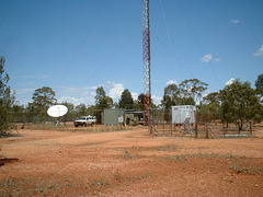
Radiocomms links and TV broadcast site. The satellite dish receives program from the public broadcaster which is transmitted to the surrounding area.
2197 Trangie - Tottenham 006
| |
|
Radiocomms links and TV broadcast site. The satellite dish receives program from the public broadcaster which is transmitted to the surrounding area.


