.:madworm:.'s photos with the keyword: power supply electronics failure by design
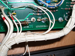
C20 just doesn't fit
| 24 May 2010 |
|
C20 was added at the bottom of the PCB. Seems like they had some problems with space.
Bad solder job
| 24 May 2010 |
|
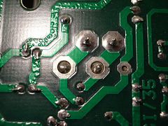
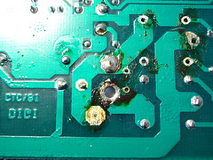
Bad solder job.
The rightmost pad should have been as large as the left ones. The wire diameter on the other side of the board is the same for all three of them.
Bad solder job
| 24 May 2010 |
|
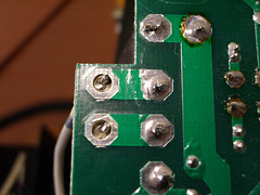
95% of the board are OK...
On the other side there are two terrible cases of "wire doesn't fit through pad".
Digital power supply
| 24 May 2010 |
|
BMOW.
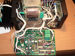
The bottom right chips are two DACs. Either they're used to drive the power transistors, or (which would be a sad thing) they're used to drive the LC displays on the front.
The two green relays are used for two thing: a) connect/disconnect the voltage from the screw terminals on the front, b) short + to - for offline current adjustment. This plays an important role when the fuses for the microcontroller blow.
Both relays are SPDT. One is connected as "normally closed", the other one as "normally open".
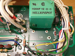
Removing a relay
| 24 May 2010 |
|
At first I thought one relay was broken, but it turned out to be a classical "failure by design". More on that on my blog.
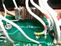
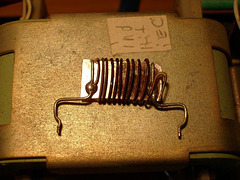
Overheated shunt resistor
Overheated shunt resistor
Overheated shunt resistor
| 24 May 2010 |
|
The left one got too hot. It was running a few hours at maximum current (about 2.8A). As I found out later, it ran in unregulated mode, as two fuses were blown. The power to the microcontroller was cut off.
After replacing the two 100mA fuses with 160mA ones it works again. I just happened to have them, but I'll need to get proper ones. The shunt resistor will have to be replaced as well, as its insulation is breaking down. I've measured it to be 0.4Ω, but I can't trust that value. Maybe the manufacturer will tell me the correct resistance.
Jump to top
RSS feed- .:madworm:.'s latest photos with "power supply electronics failure by design" - Photos
- ipernity © 2007-2025
- Help & Contact
|
Club news
|
About ipernity
|
History |
ipernity Club & Prices |
Guide of good conduct
Donate | Group guidelines | Privacy policy | Terms of use | Statutes | In memoria -
Facebook
Twitter

